Computational modelling of ray propagation through optical elements using the principles of geometric optics (Ray Tracer)
Introduction
By applying the principles of geometric optics, imaging performances of lenses were investigated via examining the propagation of optical rays through various optical systems. The optical system and its elements were modelled with an object-oriented approach using the Python programming language. Through utilising a ray bundle with specific parameters, the performances of a planoconvex lens with different orientations were analysed. The orientation with the convex surface facing the incident beam was found to be more effective at minimising the spherical aberration. This was evident from the value of the geometric RMS spot radius of 1.85 x 10^-5} m at the paraxial focus compared to 7.04 x 10^-5 m for the plano-convex orientation. This was further supported by the relatively slow rate of increase in the RMS spot radius with the beam size for the convex-plano orientation. Furthermore, by optimising the curvatures of a singlet lens with a image distance of 100 mm, the best form curvatures were approximated as 0.01417 mm^-1 and -0.00532 mm^-1 with the RMS spot radius of 6.07 x 10^-8 m, leading to a conclusion that the system was diffraction limited and the effect of diffraction was substantial when using a beam radius smaller than 13.60 mm.
Requirements
Python 2.x is required to run the scripts (except for those with name beginning with ‘ODE_’).
Create an environment using conda as follows:
conda create -n python2 python=2.x
Then activate the new environment by:
conda activate python2
Results
In an ideal case, optical rays refracting through a spherical lens can be made to converge at a single point known as the focal point. However, in practice, rays fail to converge at a single point and a blurring effect occurs. This optical effect, known as the spherical aberration, is a result of the rays propagating parallel to the optical axis through a spherical lens at different distances from the axis.$^{1, 3}$ The rays further away from the optical axis experience greater refraction and thus they intersect the optical axis slightly behind the paraxial focus before diverging (FIG. 1).
For a single lens, spherical aberration can be minimised either by changing the orientation of the lens or by carefully choosing the curvatures of the spherical surfaces into the best form. In this investigation, both cases are examined using collimated ray bundles with uniformly distributed rays of various diameters with the aim to minimise this effect.
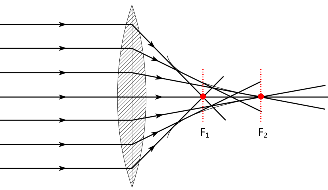 Figure 1: A lens displaying spherical aberration – the marginal and paraxial rays focus at the points F_1 and F_2 respectively.
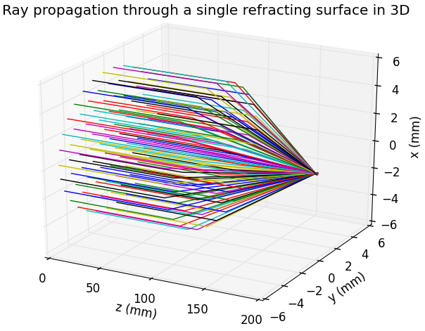
Figure 2: A ray bundle of radius 5 mm propagating through a single spherical surface with a curvature of 0.03 mm^-1 and refracting towards the optical axis.
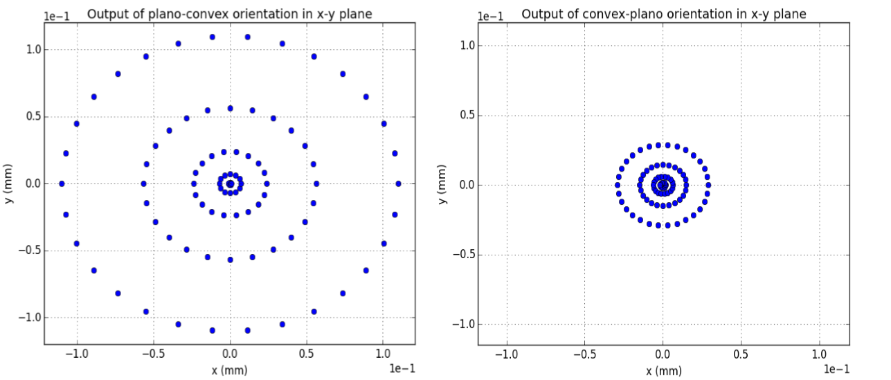
Figure 3: The non-uniform ring pattern that is shown in the figure is symbolic of the spherical aberration effect. The aberration is significantly reduced using the convex-plano orientation.
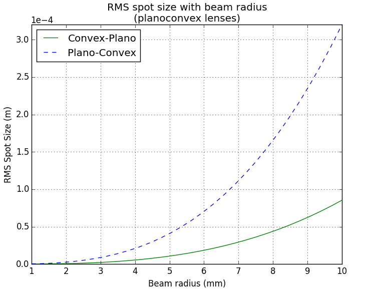
Figure 4: A graph depicting the change in the RMS spot radius at the paraxial focus with increasing beam size.
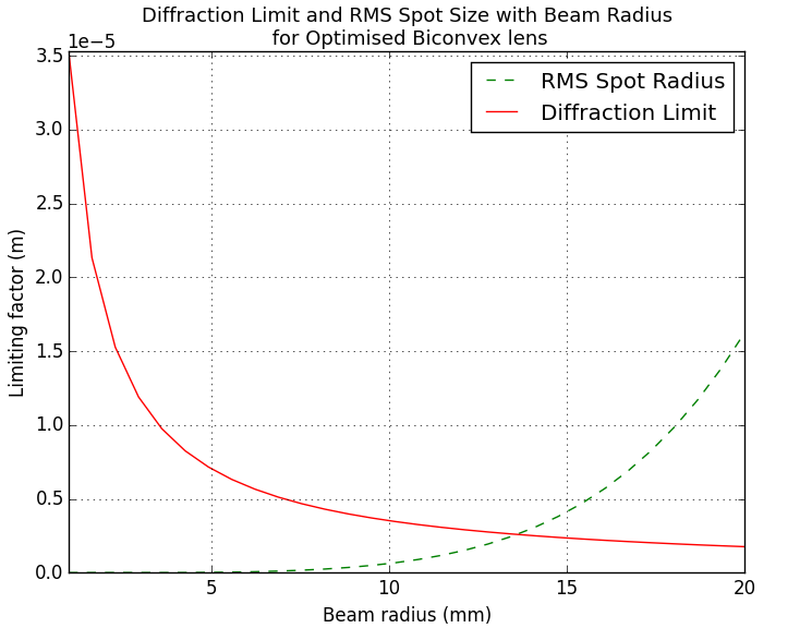
Figure 5: A graph showing the relationships of the diffraction limit and the RMS spot radius with increasing beam size.


