OctoPrint Tracer
Introduction
This plugin intends to enable direct generation of toolpaths from physical line
following. This is illustrated in this video:
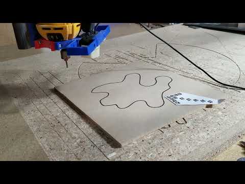
This could be useful in cases where the object is not originating from a CAD drawing, but is coming from a physical object, like cutting a piece to fit into an existing odd-shaped hole.
Installation
This has only been tested on OctoPi. It has only been tested with the latest version of OctoPrint. It might work on earlier versions based on Python 3, but the odds are low that it would work on Python 2.
The plugin depends on other Python packages but does not depend on binary applications, so it might work on Windows or Ubuntu x86 hosts. These have not been tested.
Installation on a Raspberry Pi running OctoPi should work through the plugin manager without any extra steps. Installation does take some time (approximately 10 minutes) to build numpy. (The plugin also uses OpenCV, but the dependency is automatically resolved with precompiled binaries so it does not take a lot of extra time. Only numpy has to be built.) Building numpy only takes time on the first installation. If the plugin is uninstalled and reinstalled, it is much quicker.
Preparation
The scan requires a physical printout of the “board96.png” image. This should be printed at 96 DPI. The target should be cut so the paper extends about 2mm beyond the head of the arrow. The arrow should be placed so that the line is about 10mm in front of the head of the arrow.
The line follower requires that the line to be traced is a single closed curve with no intersections (i.e. no figure 8) and with no gaps in the line. Currently the line follower is not robust to different line widths or colors, so trial and error might be necessary to find a line width that works well. The line follower is also not robust to background clutter (e.g. wood grain) so for best odds of success, the workpiece should be a relatively uniform, light color.
Manually jog the tool so that the arrow head is near the center of the field of view.
Configuration
Within the OctoPrint settings, there are options for Camera Tracer.
Image URL
The image URL is what the server uses to fetch the image. It is “from the point of view of the server”, so localhost tells it to fetch the image from itself. The default URL is “http://localhost/webcam/?action=snapshot” which on OctoPi is the webcam server.
This could be a URL for another server if for example a second Rapsberry Pi or some other server were providing images.
Scan Delay
In some circumstances an image capture may be slightly delayed relative to the physical movement. If the image is captured immediately after completion of a “G1” movement command, the image may be blurry or in the wrong position. A delay between the movement and the image capture slows down the scanning, but ensures the movement is finished.
Tool Offset X and Y
This is the relative X and Y position of the center of the camera image and the center of the spindle. These represent the movement necessary to move the cutting bit to the location where the camera is looking. Positive numbers would mean the camera location is at a +X and +Y position relative to the spindle.
Tool Diameter and Offset
Should be self-explanatory. The scanning process attempts to detect the center of the line, and the toolpath is offset by half the tool diameter, so the edge of the cut will fall on the center of the line.
The offset specifies additional “stock to leave”, so positive numbers will make holes a bit smaller and parts will be a bit bigger. Negative numbers are permitted, which makes holes larger and parts smaller.
Depth
Currently, the generator does not have a concept of a clearance plane. The generated gcode moves to the starting X/Y location, plunges to a Z coordinate of -Depth, cuts the curve, and then raises to Z=0. If Z=0 is the top of the workpiece then this will drag the tool across the top of the workpiece before cutting.
One way to prepare this is to choose a value slightly greater than the workpiece thickness, touch off the spoilboard, and set the height with G92 to be Z at the negative depth. For example, if the workpiece is 5mm, then the cut depth can be set to -7, and touch off the spoil board and set G92 Z-7. Then when the job plunges to Z=-7 it will be at the correct depth to cut all the way through the material.
Feedrate, Hole, and Climb Milling
The feedrate should be self-explanatory, and is applied to the X/Y curve cut speed. The plunge feedrate can’t currently be specified separately and is 1/5th of the X/Y feed rate. Note that the feedrate is specified in mm/min.
The hole checkbox controls whether the toolpath is offset inward (for a hole) or outward (for a part) so the dimension of the cut is correct.
Climb milling controls whether the cutting path performs climb milling or conventional milling. A climb-milling hole will cut counter-clockwise around the perimeter, while a conventional-milling hole will cut clockwise. For parts, these are reversed, so a climb milling part will be clockwise and a conventional milling part will cut counter-clockwise.
Operation
To begin the scan, first manually jog so that the arrowhead is near the center of the camera field of view. The location does not have to be precise.
On the Camera Tracer tab, click “Start Trace”. This will begin the process, and if all goes well, it should first move in the +X direction, then +Y, and then move to the line and move in steps around the curve. It should follow the curve once around, and then stop. After it stops, refresh the list of uploaded gcode files, and the newly generated file should appear there.
If at any time during the scan, things are not going properly, you can click “Cancel” from the Camera Tracer tab, and it will stop the process. If the tracing is proceeding and suddenly reverses direction, it indicates that the software got confused about which way is ‘forward’ and is tracing the line in the wrong direction. If the tracing makes an entire loop and begins on a second lap, it means that it has failed to detect that it has gotten back to the starting point. In either of these cases, it would make sense to cancel and try again from the beginning.
Diagnostics
The octoprint log file may contain useful information if something goes wrong during processing. In addition, the captured images may be downloaded in a zip archive by going to the url “/plugins/tracer/last_zip”. These may not be very informative on their own, but with an offline replay scaffolding, perhaps they could reproduce the error and provide some insight for a future fix.


