MacroPact
rPico KMK powered macropad with IPS screen
Build/Coding: kbjunky ( In case of any problems hit me up on Discord kbjunky#6476 or Reddit /u/kbjunky)
BOM
| Item | Count | Example |
|---|---|---|
| USB-C Female Breakout | 1 | Link |
| 28AWG 10 Pin Flat Ribbon cable (Rainbow) | 5m | Link |
| M2/4mm heat insert | 8 | Link |
| Raspberry Pico | 1 | Link |
| WS2812 RGB Strip | min 7 diodes | Link |
| 240x240 IPS/TFT 1.3" screen | 1 | Link |
| 12mm Rotary Encoder with switch | 2 | Link |
| Kailh Choc V1 Switch | 17 | Link |
| Choc V1 Keycaps | 17 | Link |
| 1N4148 Fast switching diode through hole | 19 | Link |
| 0.1mm copper jumper wire | 1 | Link |
| M2/4mm flat head screw | 4 | Link |
| M2/8mm flat head screw | 4 | Link |
| 15x16 Knob | 1 | Link |
| 25x17 Knob | 1 | Link |
| 6x2 antislip pads | 4 | Link |
On top of that you'll be needing:
- Soldering iron
- Rosin core solder wire (anything between 0.5mm to 1mm, preferable with lead 'Pb')
- Sharp tool to remove supports from 3D printed parts
- Wire stripper but a normal knife will also do the job
- Hot glue gun
- Soldering flux or flux marker
Remarks
Be sure to order same shaft type encoder/knob. Either Knurl or Flat(D-Type).
0.1mm copper wire is used to wire the switch matrix. It's enameled so there's no risk of shorting when crossed at the same time being very easy to solder unlike tranformer core enameled wires.
Keycaps can be ordered from Kailh Official store on Aliexpress. A better alternative is MKUltra Set.
Use flux on wires before soldering the tip.
Build guide
Setup CircuitPython
Follow this guide in order to have CircuitPython up and running on your Raspberry Pico. When it's installed correctly after plugin it in you should be able to see an additional drive named CIRCUIT_PYTHON or similar. At this point you can just copy paste the content of src directory onto the newly installed drive. This will cause rPico to reboot and keyboard firmware should be running.
3D Printing
Print the pieces in any color that you like, but best if:
- Bottom is non shine through color (only the glow insert is meant to pass the light)
- Glow insert is transparent filament
- Top plate is also non shine through (if you opt for a white or similar color then you'll have to cover the bottom side with tape/paint to prevent the light from shinning through)
Top plate:
- Infill 100%
- Layer height 0.2
- Print facing down to get a nice smooth surface (especially if you're printing on a mirror)
Bottom:
- Infill 30%
- Layer height 0.1
- Support ON
Glow insert:
- Infill 100%
- Layer height 0.1
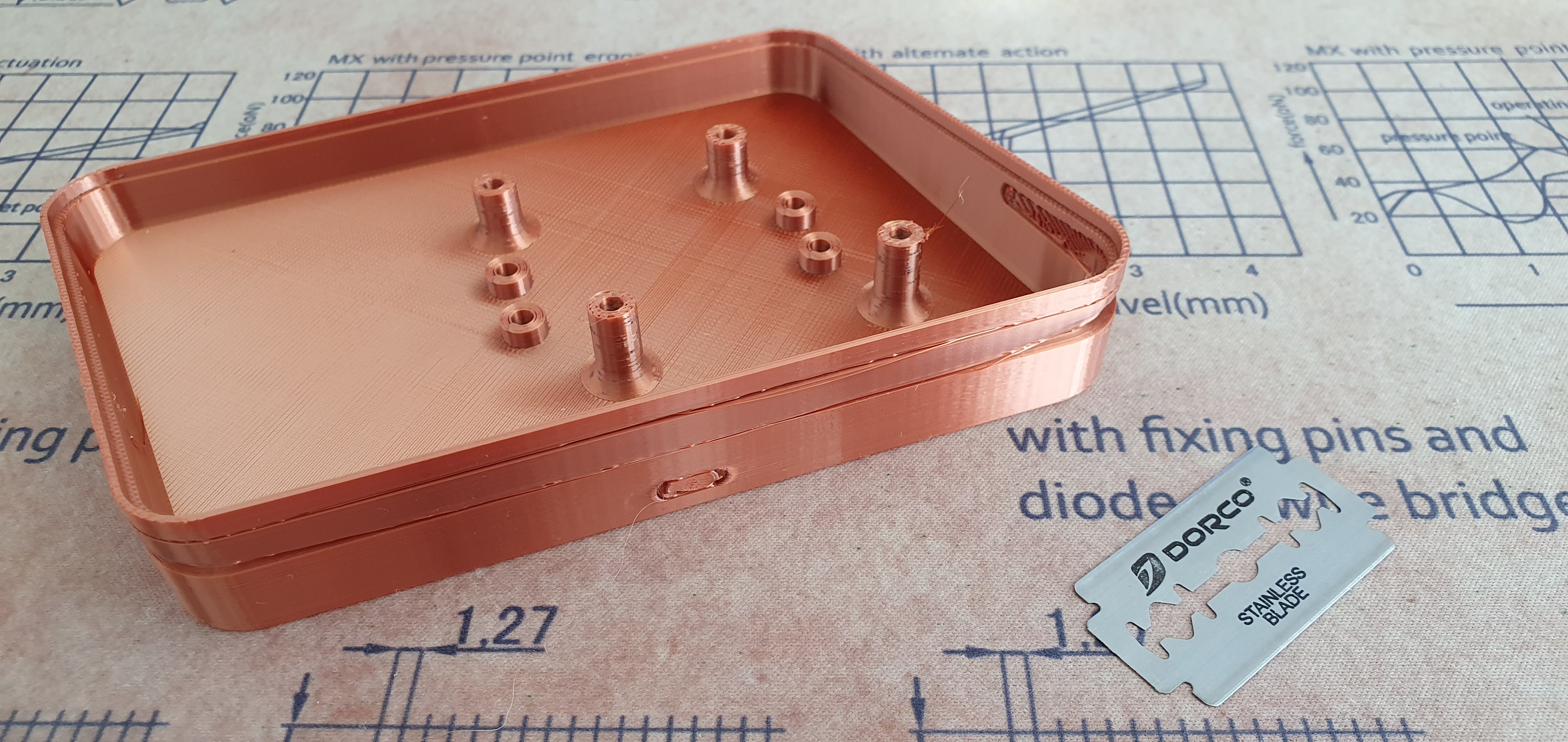
Printed bottom part should look like this. Use a sharp tool to remove supports from USB port and glow insert slot. Use glue/hot glue to fix the the glow insert in place.

Use soldering iron and push in the heat inserts into designated spots.
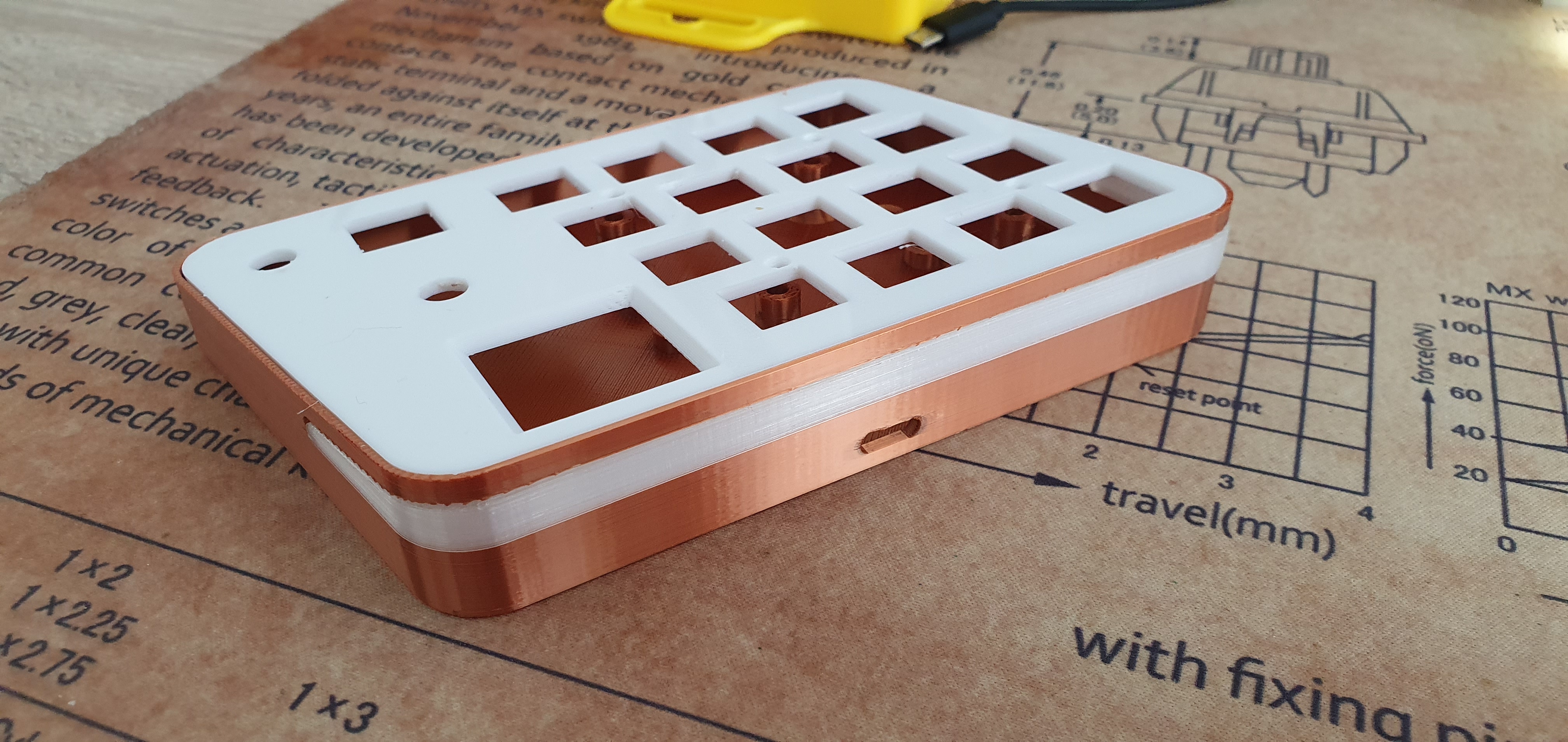
At this point you can also try attaching top plate. It should clip in. Check if all holes align etc.
Wiring
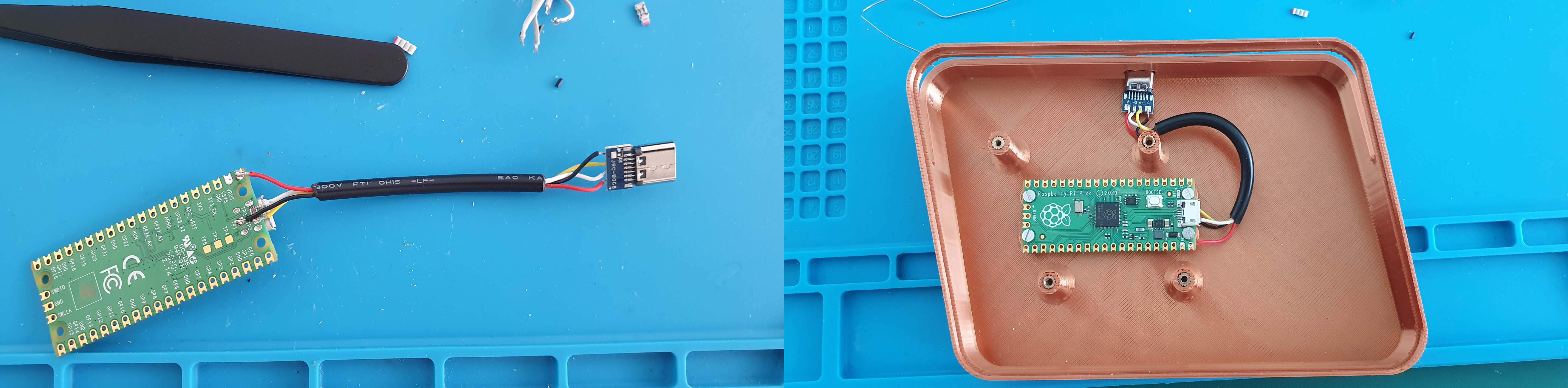
Start with connecting USB-C extension.
Connection diagram:
| rPico | USB-C |
|---|---|
| VBUS | V+ |
| TP2 | D- |
| TP3 | D+ |
| TP1 | GND |
Check if wiring is correct by plugging in the rPico and checking if the internal drive has showed up. If it's OK then screw in the MCU into the bottom part of the macropad with M2/5mm screws and insert the USB-C socket into the hole at the back. Secure it with hot glue.
Insert switches, encoders into the top plate. Secure the encoders with washers and screws that came with it. Here I have used my own amoebas but you will be fine with just bare switches.
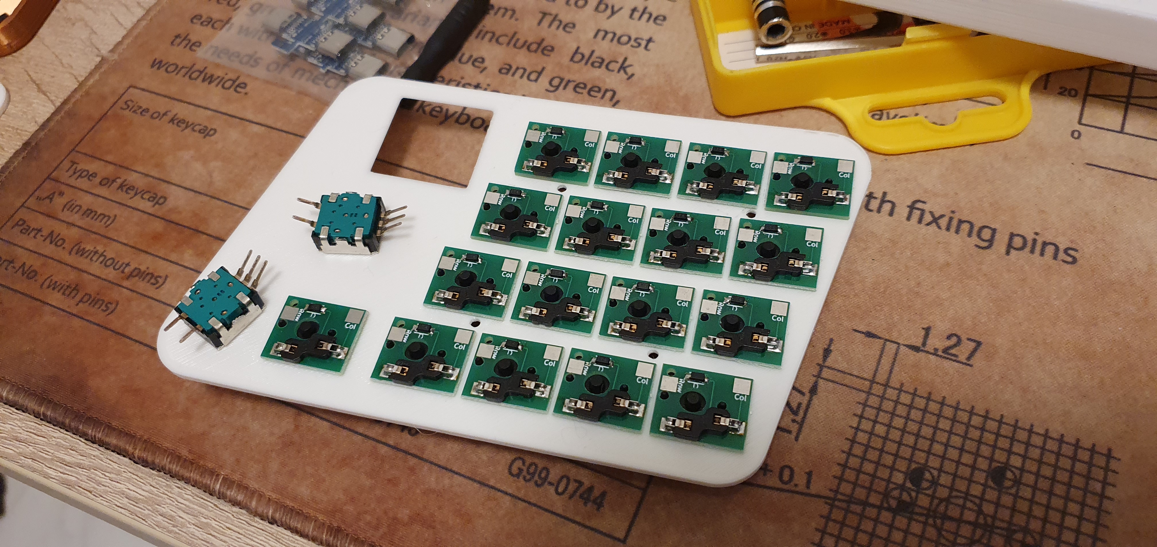
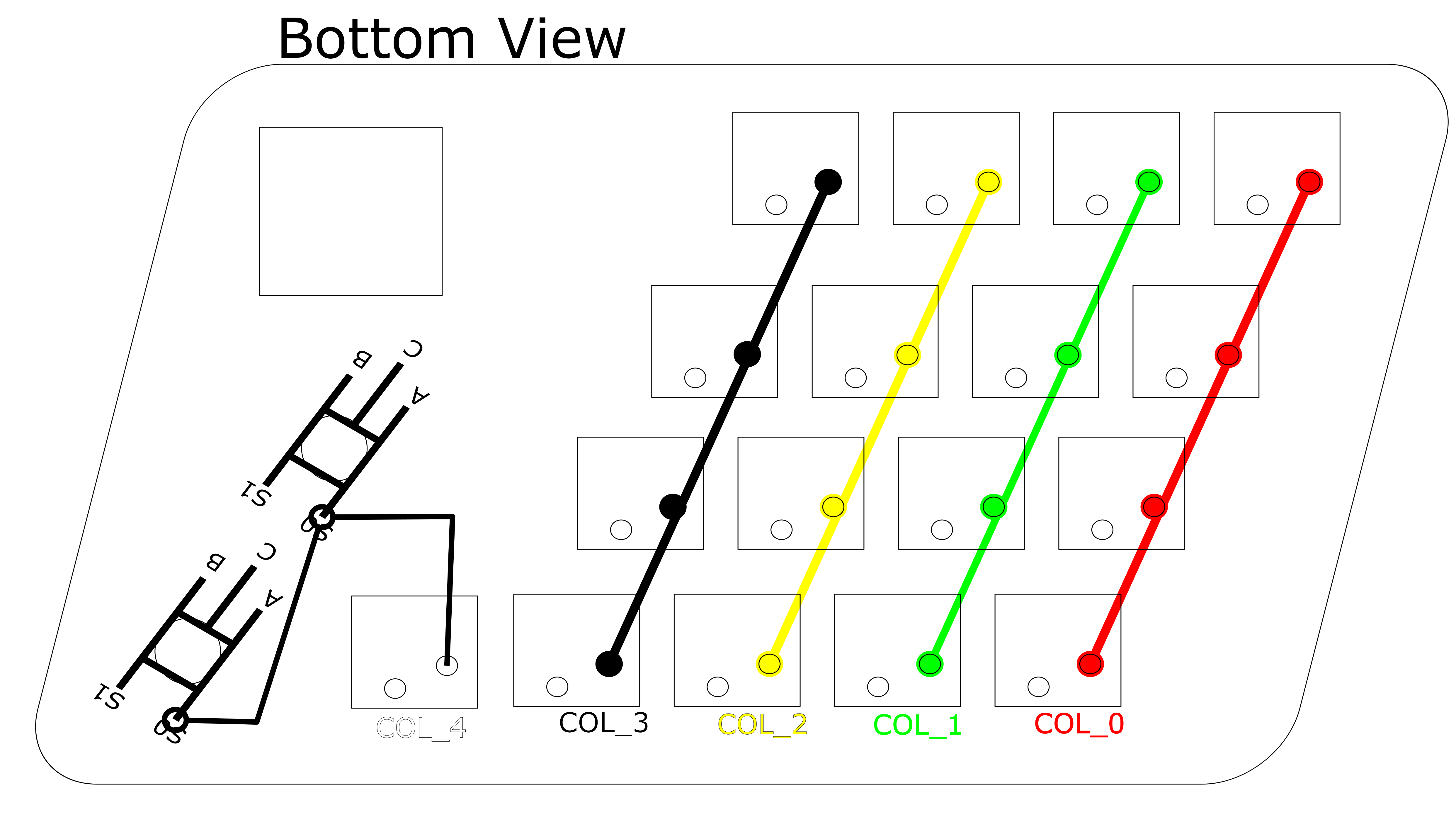
Follow the diagrams below for wiring the matrix columns.
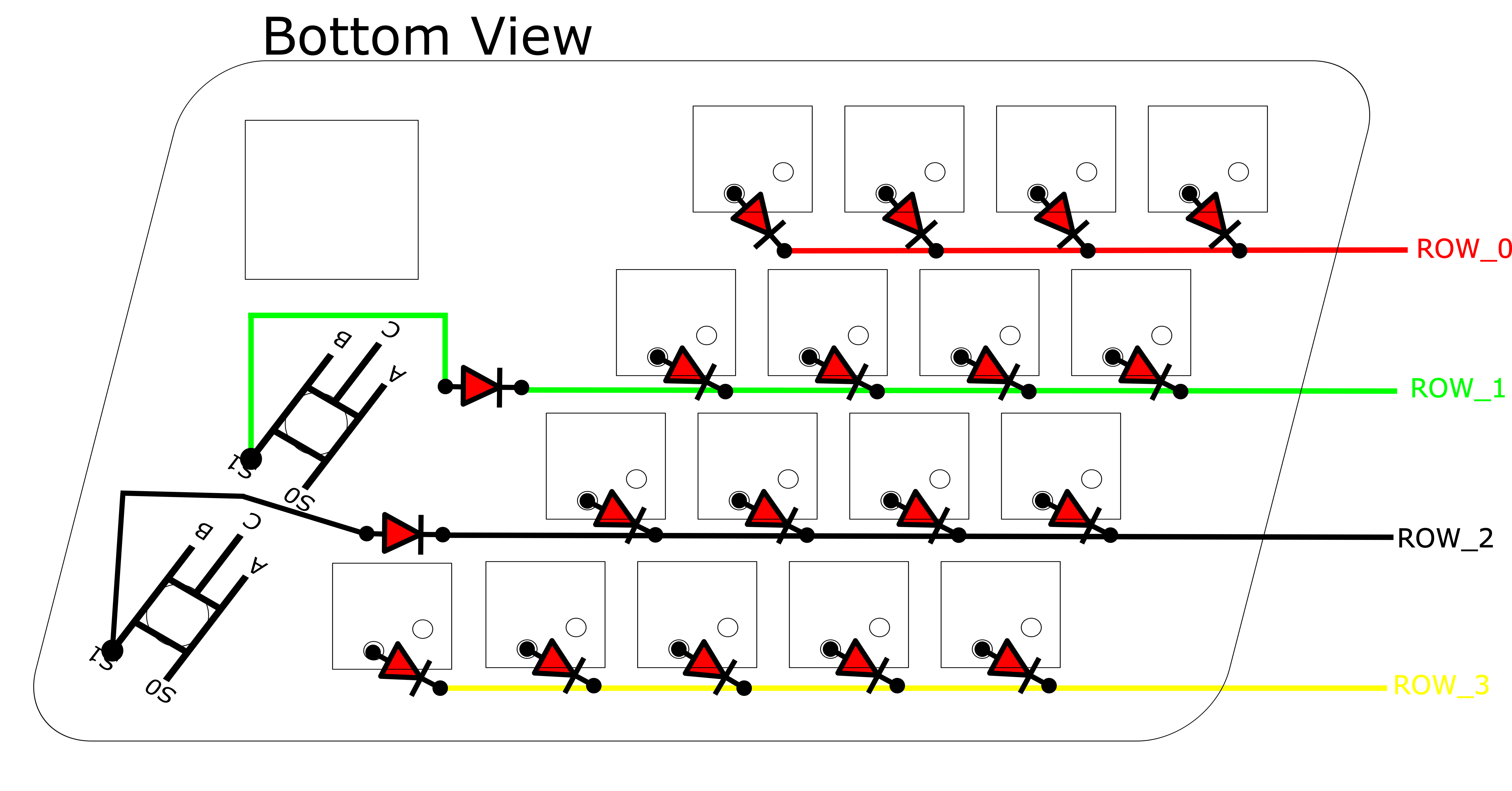
And matrix rows.
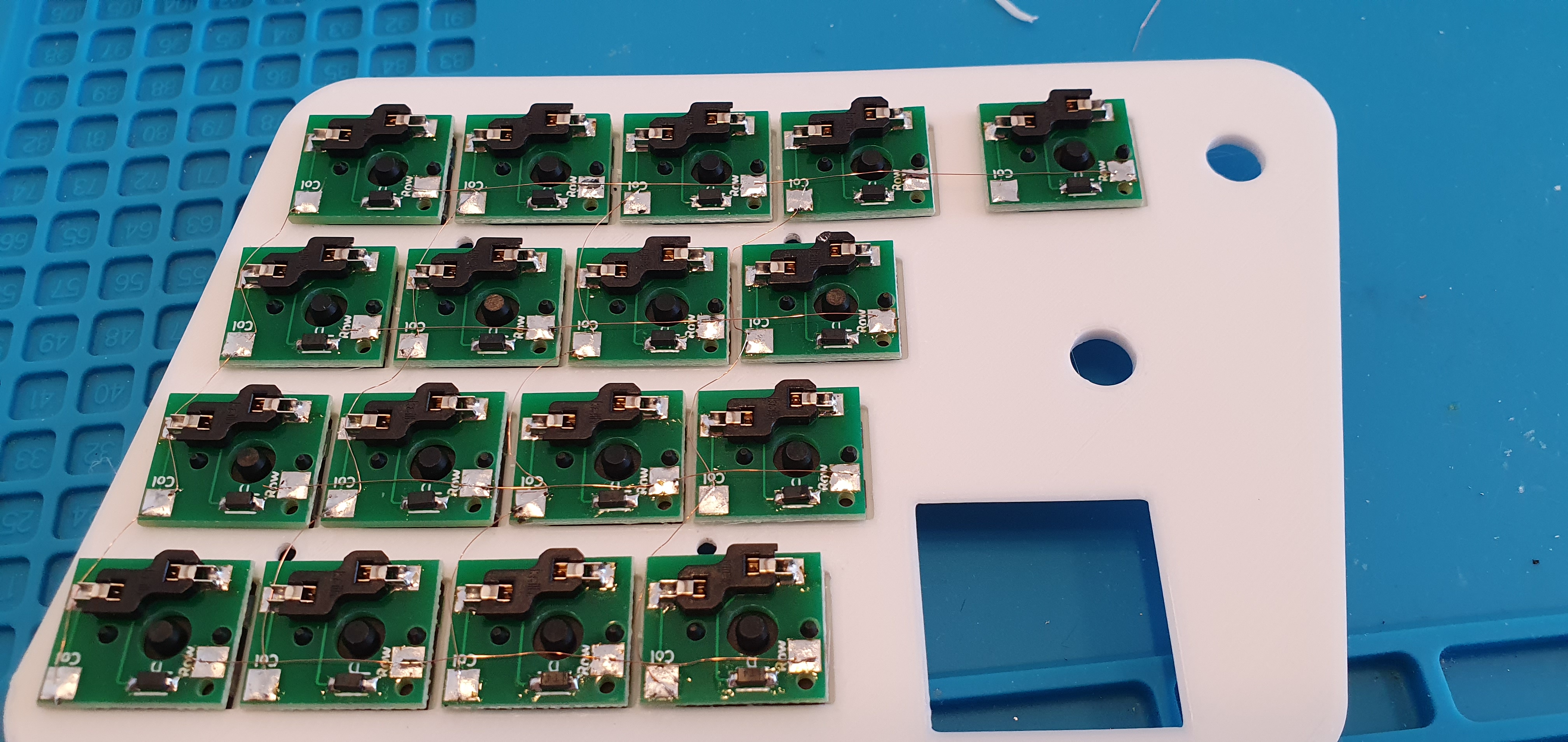
This is how it looked like in my case.
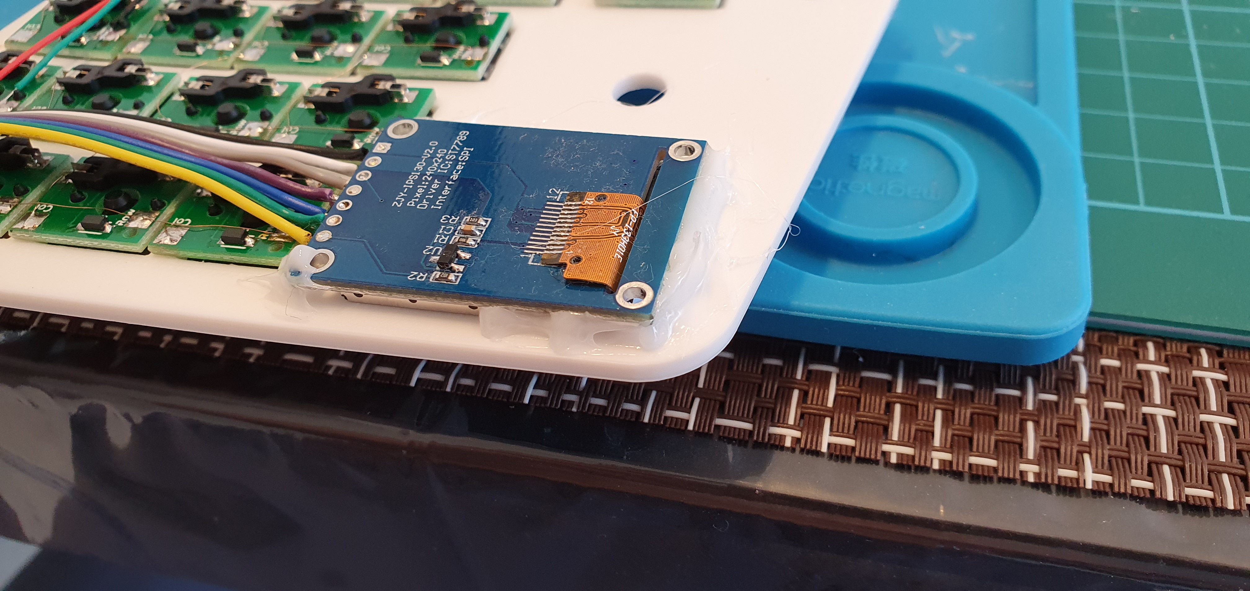
Now is a good time to attach the IPS screen to the top plate. Follow the below diagram in order to connect the IPS with rPico (Dotted wire is white).

Once this is done it's time to test it and align it properly. After booting the keyboard it should display visual help for the first layer (I've used a different image, just a white rectangle to mark the edges of the screen, but now when firmware is all done you can use default 1st layer visual guide).

Align the display part of the screen with the slot and secure it with hot glue from he bottom. (Don't mind the diffrent colors on the photo it was a temporary connector back then).
With that out of the way we can proceed and connect our matrix with the MCU. Follow the below table and diagrams posted above for proper wiring.
Columns
| Matrix | MCU |
|---|---|
| COL_0 Red | GP15 |
| COL_1 Green | GP14 |
| COL_2 Yellow | GP13 |
| COL_3 Black | GP12 |
| COL_4 White | GP11 |
Rows
| Matrix | MCU |
|---|---|
| Row_0 Red | GP16 |
| Row_1 Green | GP17 |
| Row_2 Black | GP18 |
| Row_3 White | GP19 |
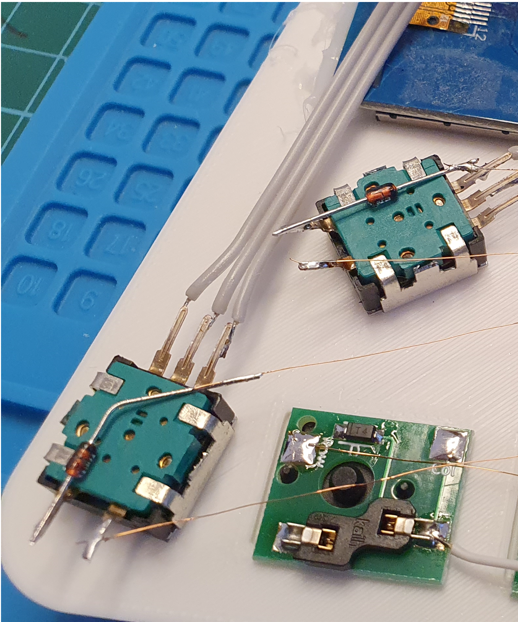
Last thing that is left are encoders. Clip the mounting legs on the sides, we won't be needing them (thick ones). Connect 'C' pads (the one in the middle of the side with three legs) to any GND on the MCU. Then connect pads A and B from each encoder according to this table.
| Row_1 Green Encoder | MCU |
|---|---|
| Pad A | GP1 |
| Pad B | GP0 |
| Row_2 Black Encoder | MCU |
|---|---|
| Pad A | GP2 |
| Pad B | GP3 |
And last but not least RGB. Cut the amount of diodes that suits you best. I would recommend anything between 7 to 9 or 11. Wiring is quite simple. Use the GND near the data pin on the MCU.
| RGB | MCU |
|---|---|
| VCC | VBUS |
| Data | GP28 |
| GND | GND(AGND) |
And that's it. If all went well your MacroPact should be functional. Connect it and check. If it's all good secure remaining parts with hot glue (ie. encoders, LED strip). Attach the top plate to the bottom part and screw it in with the 8mm screws. Put on the keycaps and enjoy!
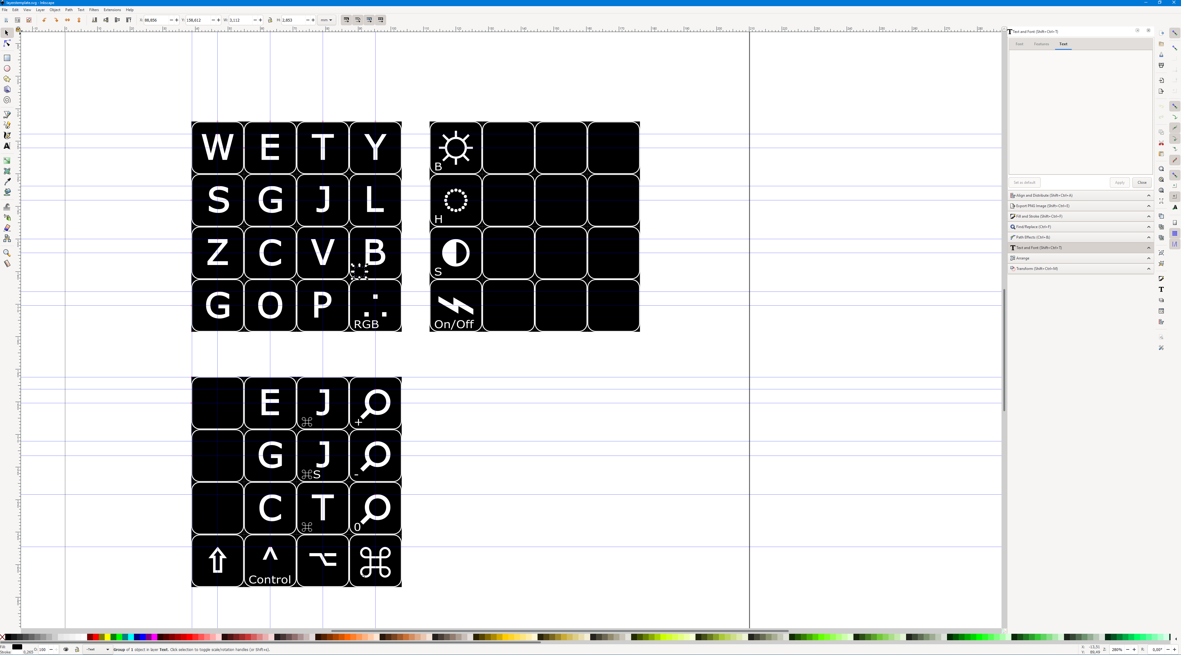
You can customize the layout anyway you want. You might want to check KMK Manual before you do. Check 'SVG' folder for a template for visual guide that is displayed per layer. You can use Inkscape for editing it and then export to PNG. In order to save space you can convert exported PNG files to low color BMP. Also note that the final picture has to be rotated 90 deg CCW.
You can edit the text for key/modifier(bottom left of each cell). Some modifiers are not visible because the stroke/fill is set to the background color. Change the color if you want the modifier to be visible. Use Unicode characters for the icons, there's plenty to choose from.
As a last step I recommend using rubber feet to prevent the macropad from sliding on the desk. Also a magnetic USB-C cable can come handy as it won't put this much stress on the socket and is very neat.


